MetrologyLab
.com
www.
The basic goal is to increase the accuracy of computer vision by meticulously modeling the geometry of a camera with lens, particularly with a wide-angle lens, for:
-
3-D triangulation accuracy in stereo and motion paralax calculations
-
Improving the alignment of lens elements during their assembly
-
Making more accurate measurements in photos/videos for various applications
The Metrology Lab app/demo is now available for general distribution with free use. Via the GUI, a user can experiment with classic machine vision functions, including precise camera calibration. For measurement, the tools are: edge locator, line fitter, arc fitter, projection, and histogram. For processing, the tools are morphology (binary and grayscale), transforms, convolutions, cross gradient filter and Sobel filter, plus more. (I can imagine the Demo’s use being a homework assignment in an introductory computer vision class.)
With its use of constructive statistical geometry and a spline model of radial distortion, the new calibration method outperforms standard solutions—such as OpenCV—in accuracy. (OpenCV's cv::solve() and cv::findHomography() make least-squares fits without weights and OpenCV uses a polynomial defined by merely three coefficients to model the radial distortion.) Use MetrologyLabDemo to calibrate any camera/lens combo by loading a PNG or BMP image of the calibration target (a sample image and a target generator in the GUI are included) and the returned information can be used in your vision application. Great for stereo. The app optionally outputs a text file containing all of the calibration values (the two 3x3 homogeneous transformation matrices, LUT’s for the two splines, the optical center point, as well as a few other values) and included is a C source file containing the relatively simple pixel-to-mm and mm-to-pixel routines that perform the transformations with correction of radial distortion. The Demo’s term-of-use is free.
I think there will be a growing interest in my robust growing calibration technique, the spline model, and the overall focus on accuracy. Use the app with your camera/lens to view the radial distortion vectors and the residual error vectors after correction.
The app logs into a server in the cloud to enforce registration: name, password, and optionally an email address. There is no verification. I just want to see how many different people are using it and how frequently, for now.
Download the zip file of the folder containing the MetrologyLabDemo.exe file and run this 64-bit app on a Windows PC.
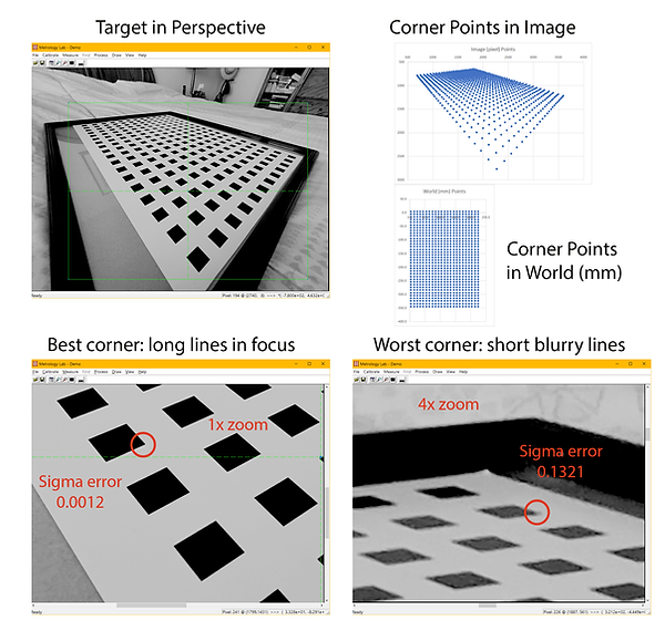
Not all points are created equal!
Radial Distortion Model
(Click on graph below for paper)

Polynomial vs Spline Model for Camera Lens Radial Distortion
(Click on graph below for paper)

This video shows the modeling of the radial distortion of a wide-angle camera (160 degree FOV). Each of the two final curves shown, extending into unknown territory beyond the circular AOI modeled, are modeled by a final parabola that blends into a line. In the pixel-to-mm case, the final line is essentially vertical. In the mm-to-pixel case, the slope is -4.44 because one bucket moves outward by 4.44 pixels.
Below are some videos, presentations and notes, older first.
Cars need 3 forward-looking cameras
Saving lives via collision avoidance is a motivation for improving 3-D vision. Click on the image to read the short article via LinkedIn.

Calibrating a Tesla Model 3’s Cameras
Early work that lead to the calibration booth idea. Download this presentation with embedded videos to open it in PowerPoint. [59MB]

Camera Calibration Booth video
A future way to calibrate all of a vehicle’s cameras with 360 degree visual coverage. Click on image to view video. [410MB]

Error Vectors
Illustrates nonlinear optical errors, explaining how error vectors are computed. Click on image to view the PowerPoint presentation. [8MB]

Fisheye Lens Calibration
The presentation shows calibration of an Eufy smart door lock’s camera and a Nikon fisheye lens (actually, a Nikon Fisheye Converter that screws onto the end of the Nikon Coolpix camera, like a lens filter). Download this presentation with embedded videos to open it in PowerPoint. [107MB]

Geometric Accuracy of an iPhone 16 Pro Max Camera
521% accuracy improvement of the iPhone 16 Pro Max’s “Ultra-Wide Camera” geometry over that of the iPhone 15 Pro Max measured! Click on image to view the PDF file. [8MB]

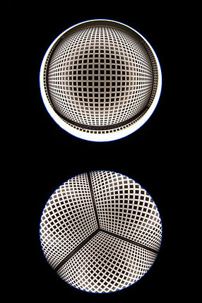
Fisheye calibration
via images of two target types
The idea here is to compute the center of the optical axis in the top image first, resulting in a radial distortion model covering only ~2/3rds of the full FOV, the inner part. Then, use an image of a corner such as would be encountered in the calibration booth described earlier to expand the reach of the radial distortion model using the pre-computed optical center. The accuracy of results does not depend on the corner's three walls being perpendicular to each other, making the setup easy. However, the lens must have a small minimum focus distance like the Nikon Fisheye Converter used earlier or the target has to be big.
[Actually, the optical center can be calculated from the second image alone. This is how the future calibration booth will work.]
Audio/Video of the Metrology Tools
The following four videos demonstrate the three basic metrology tools: edge locator, line fitter, and arc fitter. I struggled to narrate as I moved the tools about when I created the videos in January 2024. They make up a playlist on YouTube which has better viewing controls: https://lnkd.in/gRTtCHUB
Video #1: The setup. (Duration: 2.0 min.)

Video #2: Edge locators illustrated along with their use by the line and arc fitters. (Duration: 8.4 min.)
Video #3: Line fitter. (Duration: 6.0 min.)
Video #4: Arc fitter. (Duration: 3.5 min.)